UNLIMIT3D - ESP32-Breadboard-Mk2
by UNLIMIT3D
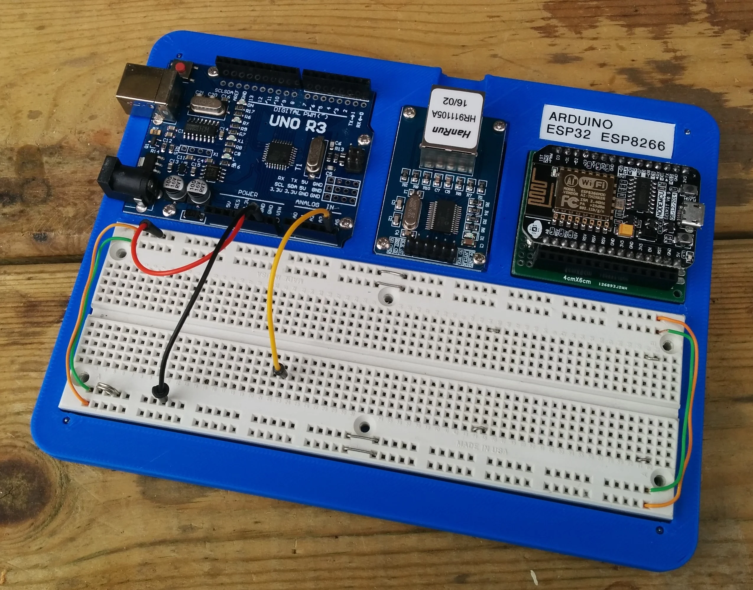
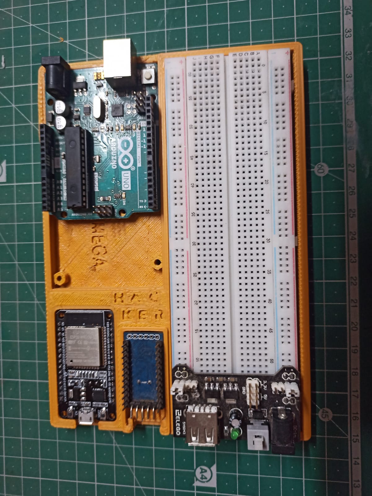
Hello world! I'm Ivan, creator of UNLIMIT3D. Surely, if you are electronic you will have realized that until now there was no "protoboard" capable of containing a development board based on the ESP 32 microcontroller, allowing the connection of its pins on both sides. This happens with all commercial breadboards, being mandatory to have to use two breadboards to make a simple circuit with that microcontroller (which can be cumbersome and confusing). This was happening until now, as I have taken the boldness to design a specific breadboard capable of supporting an ESP 32 development board, as well as supporting the other models of "Arduino" type development boards, such as: Nano, Micro Pro, Pro Mini, ESP 8266 and even Raspberry Pi Pico. The ESP32-Breadboard-Mk2 model is used in the same way as any commercial breadboard and was designed respecting commercial standards. The first part of it allows to place a power supply to supply power to the voltage buses and at the same time to power the ESP 32 independently with respect to the rest of the circuit (second half of the board). To house the ESP 32 it has 220 connection points divided into 110 points on each side of the circuit (22 x 5 point matrix on each side). The first part of the ESP32-Breadboard-Mk2 is internally separated from the second half as far as the power buses are concerned, i.e. to communicate these power buses from the first half of the board to the second half it is necessary to bridge them. The second half of the ESP32-Breadboard-Mk2 consists of independent power buses from the first half and sufficient connection points to them. However, this second half has 330 connection points (divided into two 33 x 5-point arrays on each side) for placing components, transistors, displays, ICs, potentiometers, etc. Once you print ESP32-Breadboard-Mk2 you must remove the metal brackets from any commercial breadboard and place them inside the holes of the printed model. In the channels corresponding to the power bu
Similar models

%2Fhttps%3A%2F%2Ffbi.cults3d.com%2Fuploaders%2F20215154%2Fillustration-file%2F7db9fae8-7602-4d8a-9077-06ec5ee626f6%2F8e29cfbe-0107-4881-9958-f6fcd559ab26.png)
%2Fhttps%3A%2F%2Ffbi.cults3d.com%2Fuploaders%2F13701738%2Fillustration-file%2Fcb72befe-a97a-4a90-ae1e-6ee37005f457%2F1_sqr.jpg)


%2Fhttps%3A%2F%2Ffbi.cults3d.com%2Fuploaders%2F43552274%2Fillustration-file%2F902ceb91-38be-45ce-acfd-7a593355082f%2FBreadboard-FlexCase.jpg)